Help Needed: Wiring Konnected GDO BlaQ (Security+ 2.0) to Grifco e-Drive with C10A-8 Wall Controller - RJ45 Pinout?

Hi everyone,

I’m looking for some expert help to connect my Konnected GDO BlaQ to my Grifco e-Drive garage door opener using its Security+ 2.0 protocol. I’m located in Queensland, Australia.

My Setup:

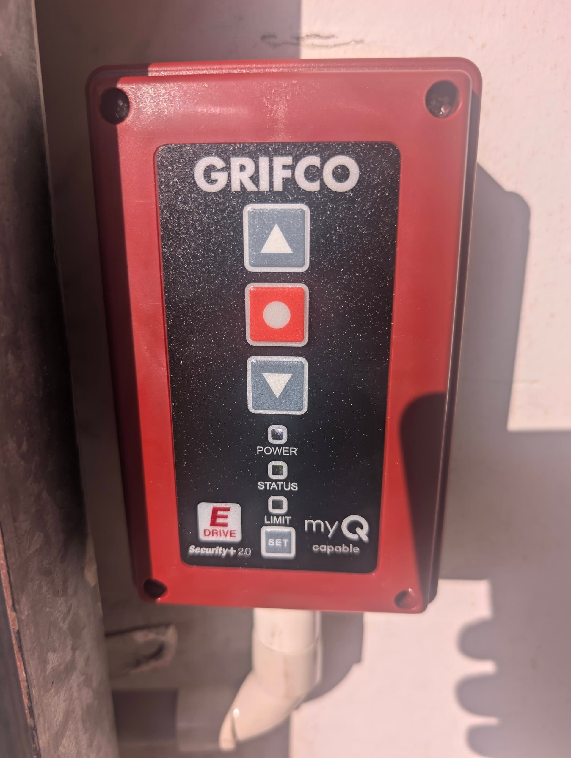
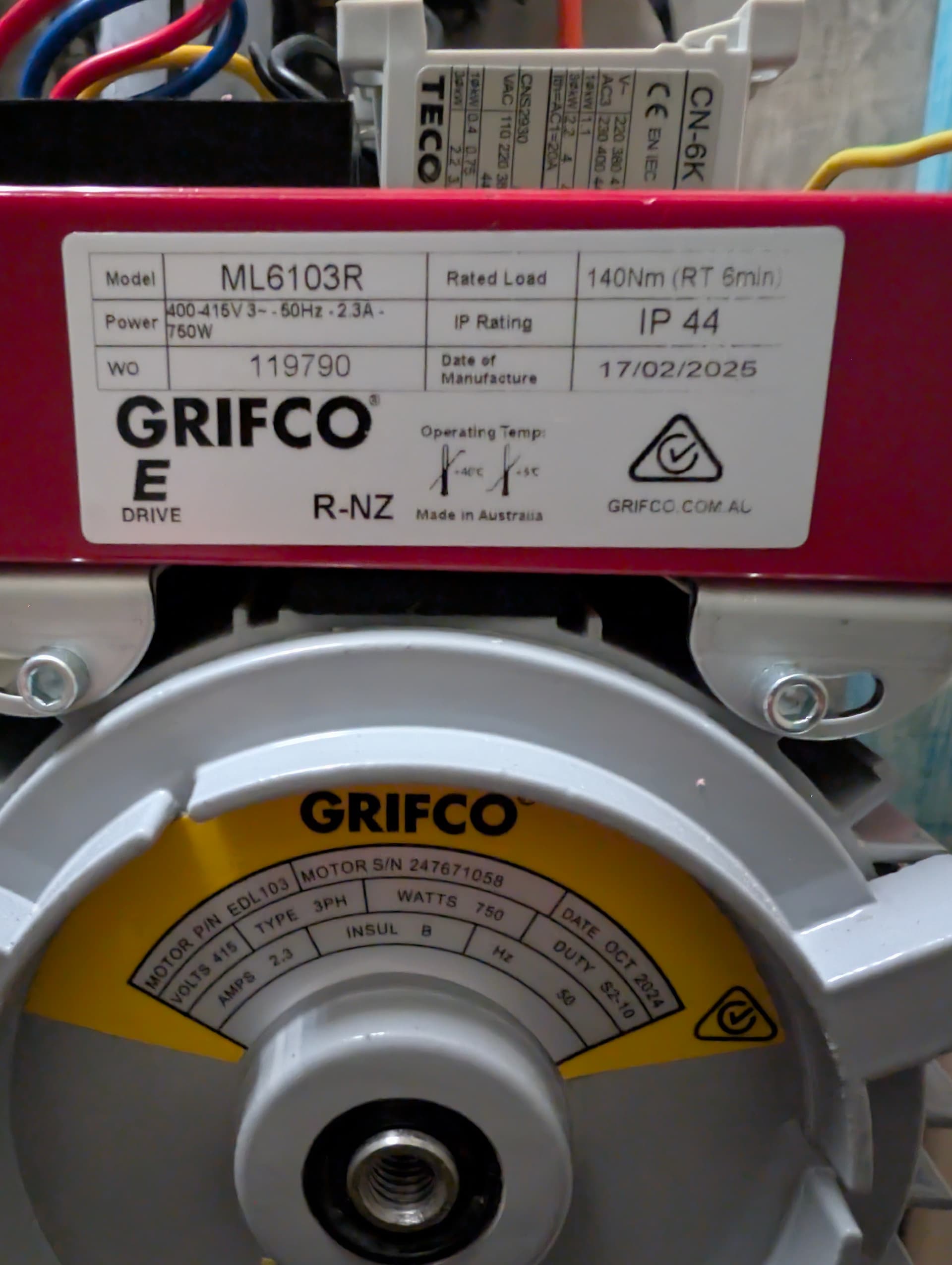
  • Opener: Grifco e-Drive, Model: ML6103R. (States MyQ ready, Security+ 2.0 printed on the wall controller).
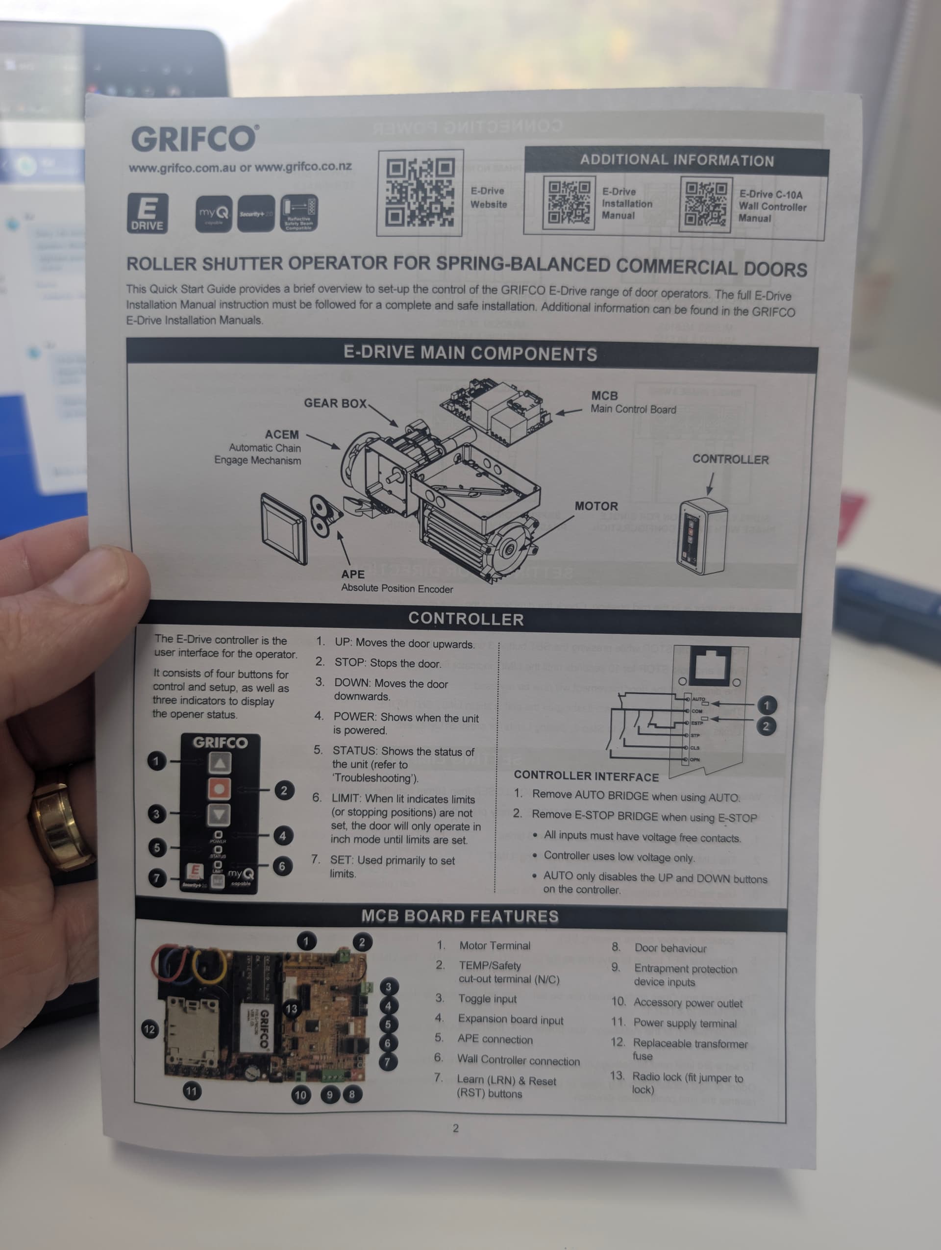
  • Wall Controller: Grifco C10A-8 (Model: C10A-8, Wall Control myQ). This unit connects to the main motor control board via an 8-core cable, which appears to be a standard RJ45 network-style cable.
    • (I’ve attached an image of the C10A-8 nameplate: PXL_20250516_045530502.jpg)
  • Smart Controller: Konnected GDO BlaQ.
  • Safety Beams: Installed and functioning correctly.

The Goal: True Security+ 2.0 Connection

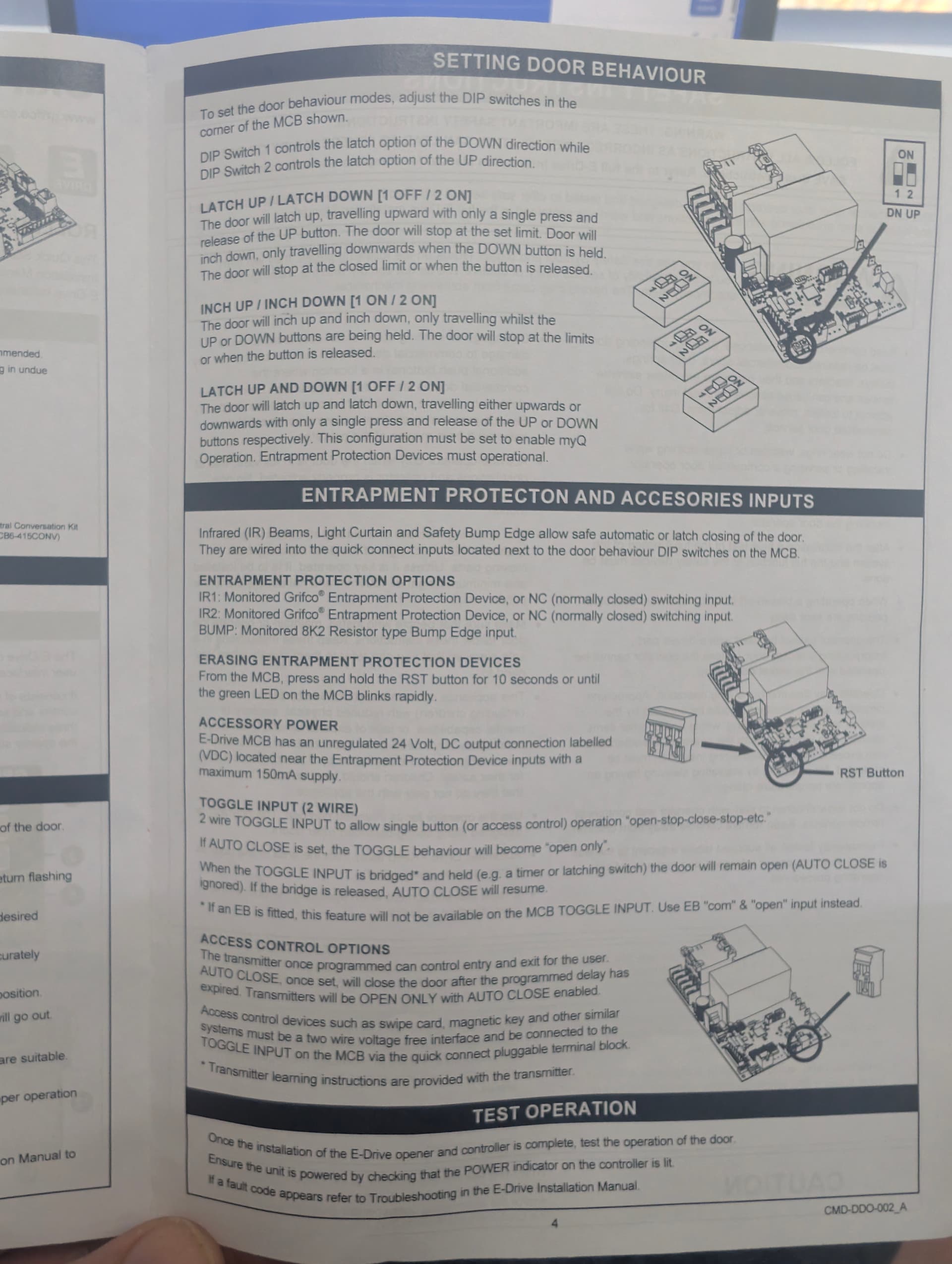
I want to wire the Konnected GDO BlaQ’s Security+ 2.0 data wires to the corresponding Security+ 2.0 data lines used by my Grifco ML6103R system. I’d strongly prefer this over using a basic dry contact "toggle mode. (which i tested by wiring into the openers TOGGLE INPUT terminals & setting the GDO BlaQ to toggle mode but couldn’t get it to work either).

My idea is to identify the specific pins within the 8-core RJ45 cable (between the C10A-8 and the motor unit) that carry the Security+ 2.0 Data signal(s) and the necessary Ground/Common reference. If I can identify these, I’m considering using an RJ45 splitter (double adapter) at the motor PCB. I would then terminate the Konnected GDO BlaQ’s S+2.0 wires into a new RJ45 plug and connect it via the splitter. This would hopefully allow both the original C10A-8 wall controller and the Konnected GDO BlaQ to communicate with the motor unit.

What I’ve Investigated:

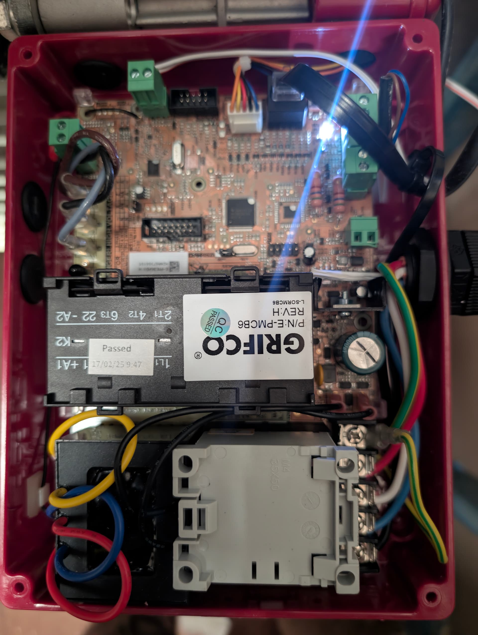
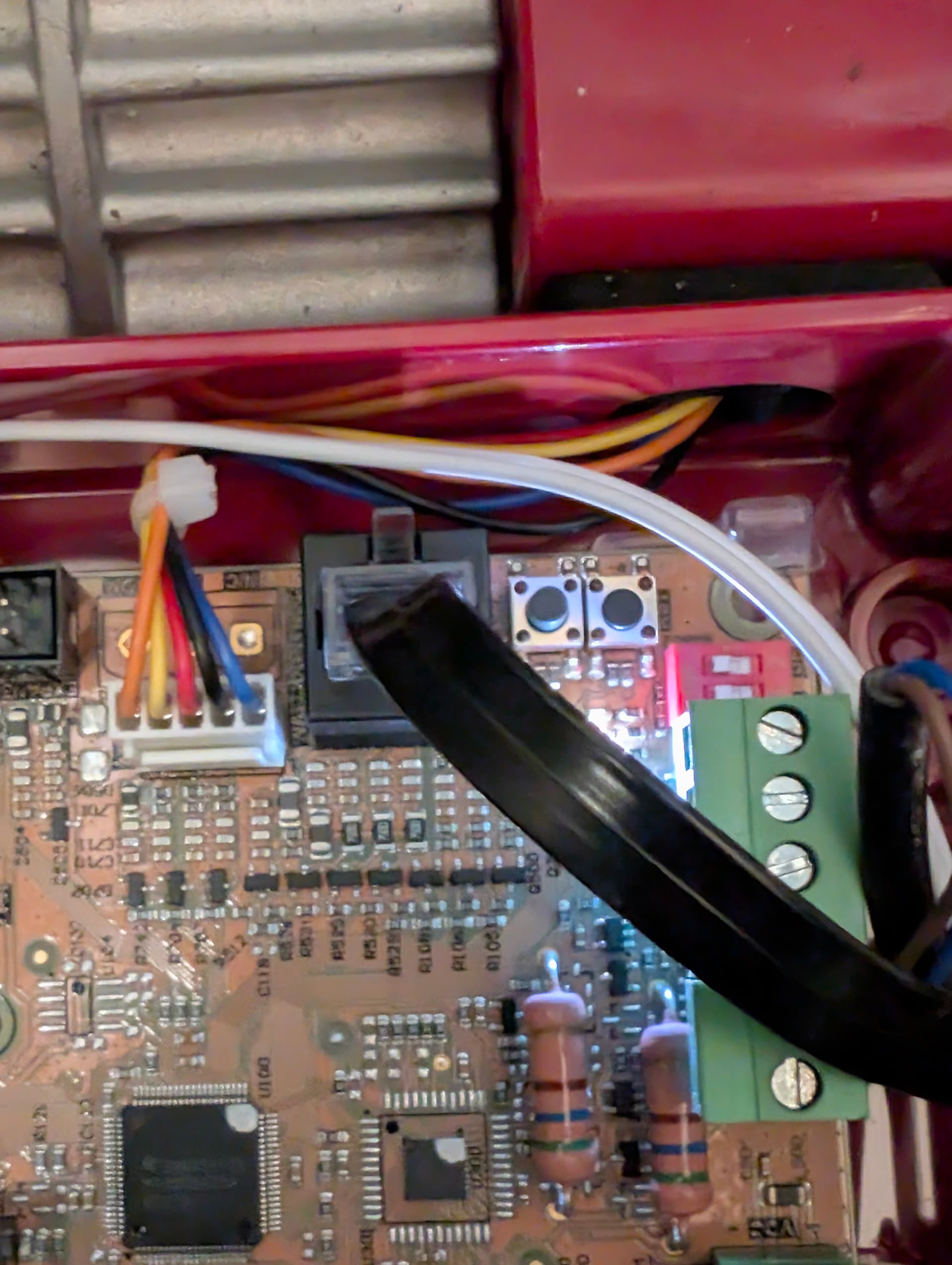
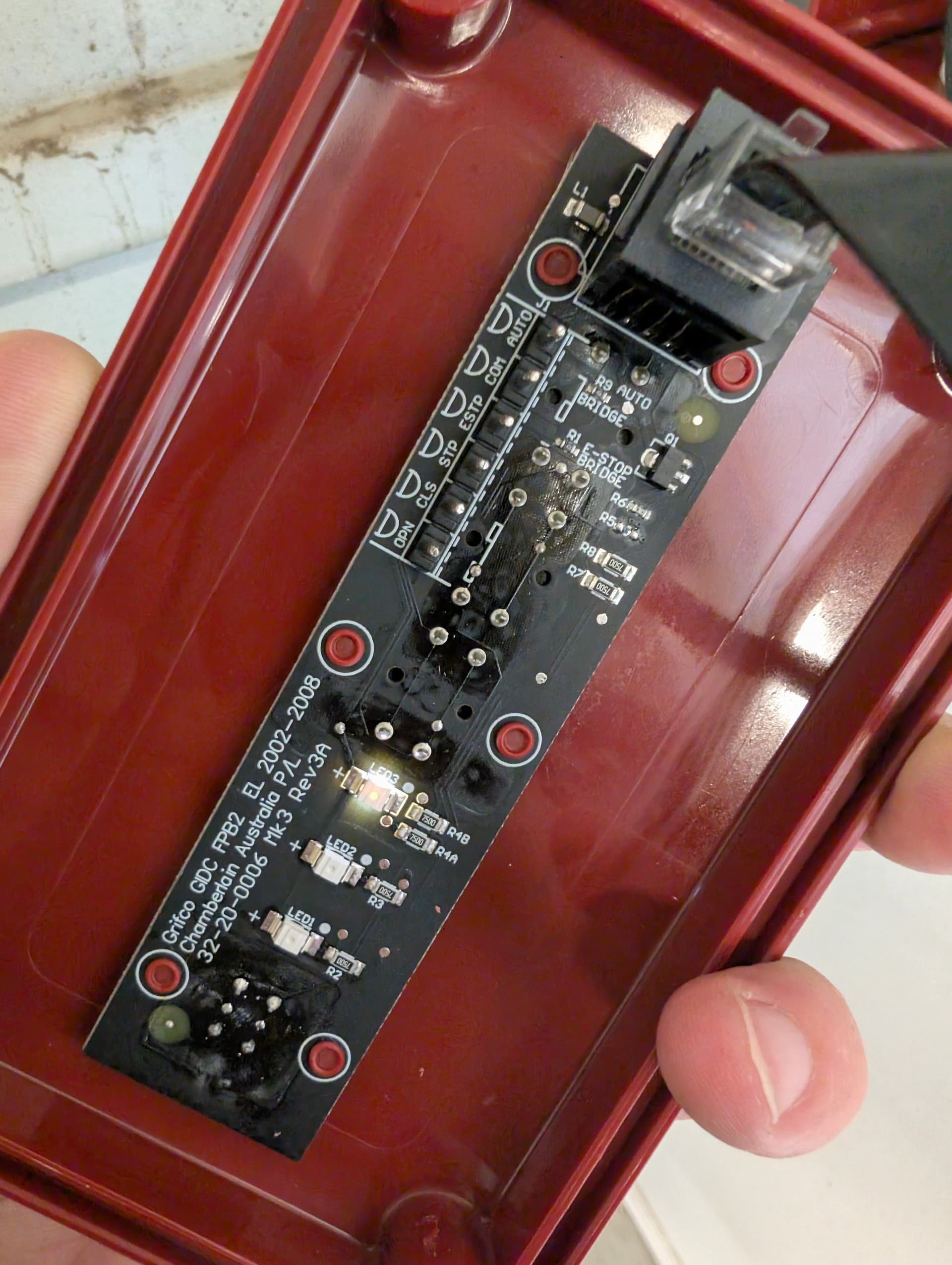
I’ve looked at the PCB inside my C10A-8 wall controller (see attached image of PCB: PXL_20250516_053849948.jpg). Based on the image, the visible solder pads that seem intended for external button inputs are:

  • OPN (Open)
  • CLS (Close)
  • STP (Stop)
  • ESTP (Emergency Stop)
  • COM (Common – this appears to be the shared reference for OPN, CLS, STP, ESTP)
  • AUTO (Unsure what this does)

While these identified input terminals (OPN, CLS, STP, ESTP, AUTO using COM) would be suitable for dry contact/toggle control, they don’t appear to be the direct lines for Security+ 2.0 data communication.

Using the Grifco schematics, identifying the exact S+2.0 data lines from these PCB pads seems speculative and risky.

My Key Questions for the Community:

  1. Has anyone successfully identified the Security+ 2.0 Data and Ground/Common pins within the 8-core RJ45 cable used by Grifco e-Drive systems (specifically model ML6103R or similar) with controllers like the C10A-8? A pinout diagram for the RJ45 carrying S+2.0 would be incredibly helpful!
  2. Are there known, dedicated screw terminals on the main Grifco e-Drive ML6103R motor unit’s control board for Security+ 2.0 accessories (equivalent to the Red/White terminals the BlaQ expects)? If so, where should I be looking? (A photo of your motor unit’s terminal block would be very helpful if you have one!)
  3. If using an RJ45 splitter at the motor unit, is the Grifco system likely to support two Security+ 2.0 control devices (the C10A-8 and the GDO BlaQ) operating in parallel?
  4. Any general advice or success stories with integrating Konnected GDO BlaQ (or similar third-party S+2.0 devices) with Australian Grifco e-Drive openers, particularly the ML6103R, would be highly valued.

I’m comfortable making up an RJ45 plug if I can get reliable pinout information. I’m trying to get the best possible integration and avoid any damage to my equipment.

Thanks heaps for any insights!


Hi everyone,

I’m hoping someone in the Konnected community can offer some guidance. I’m trying to connect my new Konnected GDO BlaQ to my Grifco e-Drive garage door opener (Model [If you know the specific e-Drive model, add it here, e.g., ML5102]) here in Australia. My goal is to use the full Security+ 2.0 functionality of the BlaQ.

My Setup:

  • Opener: Grifco e-Drive (MyQ ready, Security+ 2.0 printed on the wall controller).
  • Wall Controller: Grifco C10A-8 (Model: C10A-8, Wall Control myQ, Date of Manufacture: 12/02/2025 - as per attached image PXL_20250516_045530502.jpg). This controller connects to the main motor unit via an 8-core cable (looks like a standard network/RJ45 cable).
  • Smart Controller: Konnected GDO BlaQ.
  • Safety Beams: Installed and working directly with the motor unit.
  • Current Konnected GDO BlaQ Logs (when attempting to sync, previously connected to a toggle input): Synced: false, protocol: Security+ 2.0 Client ID: 1641, Rolling code: 3042 Rolling code set to 3142, retryng sync This shows the BlaQ is trying to establish a Security+ 2.0 connection.

The Challenge: Identifying Security+ 2.0 Wires

I want to connect the Konnected GDO BlaQ’s Security+ 2.0 wires (typically Red & White) directly to the Security+ 2.0 data lines from my Grifco e-Drive motor unit. The C10A-8 wall controller successfully communicates with the motor unit using Security+ 2.0 over its 8-core RJ45 cable.

My idea is to identify the correct pins in the RJ45 cable/connector that carry the Security+ 2.0 Data and Ground/Common. Then, I could potentially use an RJ45 splitter/double adapter at the motor PCB end. I would terminate the Konnected GDO BlaQ’s Security+ 2.0 wires into a new RJ45 plug and connect it via the splitter, allowing both the C10A-8 and the GDO BlaQ to be connected (if the system supports two Security+ 2.0 control devices in parallel).

What I’ve Found So Far:

I’ve opened the C10A-8 wall controller and taken a photo of the PCB (see attached image PXL_20250516_053849948.jpg). On the PCB, I can see an RJ45 jack and several labeled solder pads:

  • OPN, CLS, STP, COM (likely for dry contact inputs)
  • GND (Ground)
  • RBK +V (Positive Voltage from motor unit)
  • D1 (Potentially a Data line)

While D1, GND, and RBK +V are candidates, I’m hesitant to connect directly to these PCB pads for Security+ 2.0 without knowing their exact function and the full pinout of the RJ45 connector used by Grifco for this controller. The Konnected GDO BlaQ typically expects to connect to Red & White terminals on the motor unit.

My Questions for the Forum:

  1. Has anyone successfully wired a Konnected GDO BlaQ (or a similar Security+ 2.0 third-party device) to a Grifco e-Drive system that uses the C10A-8 wall controller (or similar RJ45-connected controller)?
  2. Does anyone know the RJ45 pinout that Grifco uses for its Security+ 2.0 wall controllers like the C10A-8? Specifically, which pins/wires carry the actual Security+ 2.0 data signals (equivalent to the Red & White wires the BlaQ uses) and the necessary ground/reference?
  3. Are there dedicated terminals on the Grifco e-Drive motor unit’s main control board specifically for Security+ 2.0 accessories that I should be looking for, separate from the RJ45 port for the main wall controller? (My motor unit is [briefly describe accessibility or any visible terminals if you’ve looked]).
  4. Any advice on using an RJ45 splitter for this purpose? Would the Grifco system likely support two Security+ 2.0 control devices (the C10A-8 and the GDO BlaQ) operating in parallel on the same lines?

I’d prefer not to use the basic “toggle mode” on the GDO BlaQ as I want the full integration and feedback that Security+ 2.0 can offer (and for the BlaQ to correctly report its synced status).

Any help, wiring diagrams, pinout information, or shared experiences would be massively appreciated! I’m trying to avoid any trial-and-error that could damage my opener or the Konnected device.

Thanks in advance!


![PXL_20250516_045530502|376x500]


(upload://298npFnRTQ08vOaXqL1nkCwBDuL.jpeg)

The short answer is – I don’t know.

This looks more like the U.S. equivalent of a commercial grade LiftMaster opener rather than a residential garage opener. We’ve had a few users experiment with these types (see Medium Duty Logic MJ5011U not working) but so far no confirmed success. I think the wireline protocol used by the commercial grade products is different from those used by the residential line, despite using the same “Security+2.0” branding.

You are likely right that OPN, CLS, STP, COM are dry-contact inputs for the various directional controls. The GDO blaQ uses a serial data method of communication, so my best guess, if it were to work at all, would be via the D1 terminal and COM. But again, I’ve never tested with this model/brand so your guess is as good as mine.

Report back if you find anything interesting!