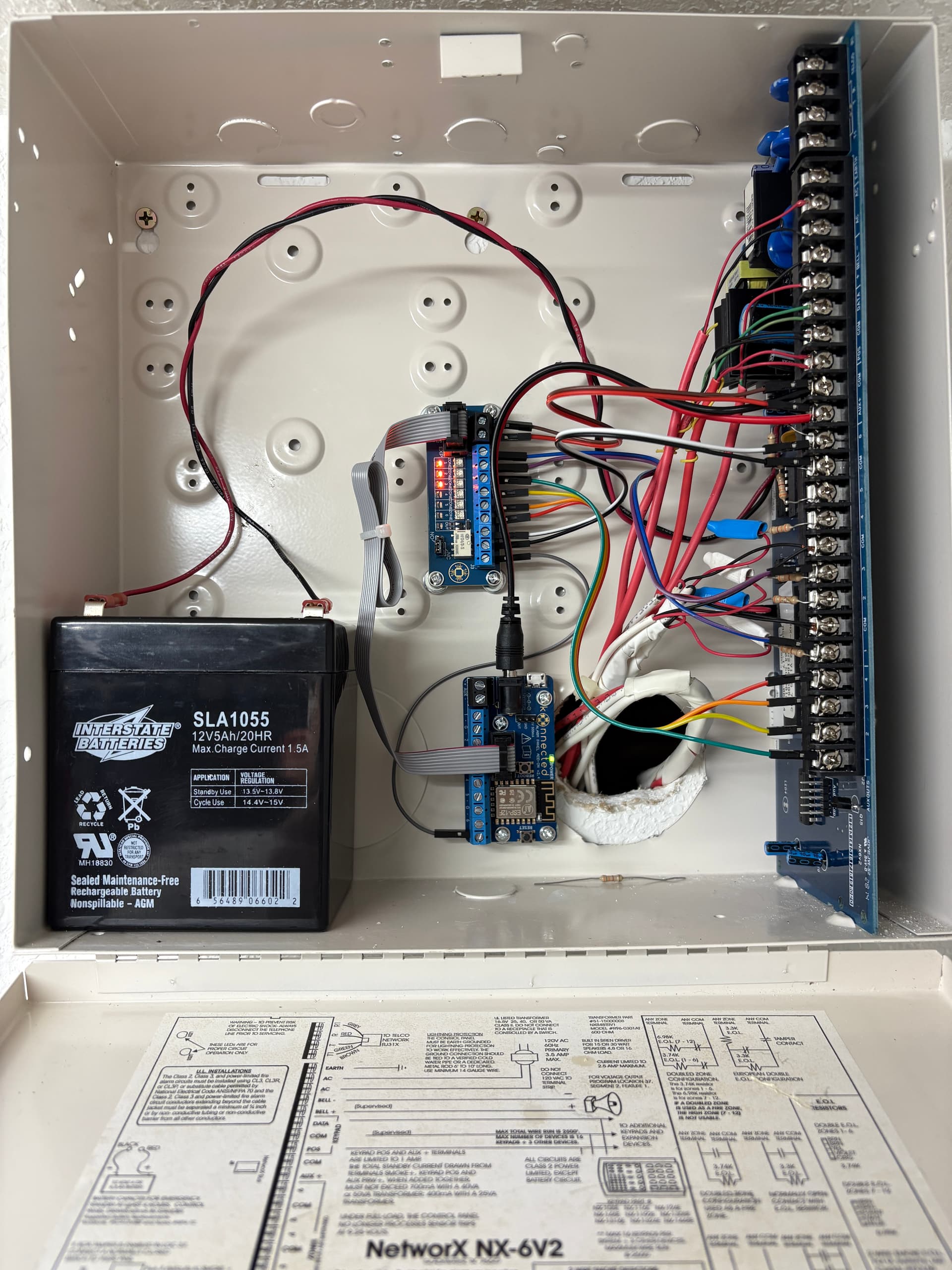
I have noticed the lack of detailed information on programming the NetworX NX-6V2 alarm system. So, I have created the following guide. Except for the key switch these instructions should apply to the NX-4V2 and NX-8V2 as well. Notice in the photo below that I powered the Konnected Alarm Add-on Board and Interface Module from the Auxiliary Power output of the NX-6V2 board. This allows me to utilize the NX-6V2’s backup battery. If the output voltage of your existing battery output voltage is below 3.45V or the battery is more than five years old, I recommend replacing it. The Interstate Batteries SLA1055 is around $25 from Amazon. Also note that I placed the Alarm Add-on Board’s Wi-Fi antenna near the cable entry hole at the back of the enclosure. This gave me adequate signal strength without mounting the Alarm Add-on Board outside the cabinet. The optional magnetic standoffs are worth purchasing because they allow you to fine tune the locations of the Konnected boards.
I will refer to pages from the NX-6V2 Control Panel Installation Manual. The manual for the NX-6V2 can be downloaded here: https://kmtsystems.com/wp-content/uploads/2018/06/I-NX6V2-IM-Rev-C-Installation-Manual.pdf
My system only uses four of the six NX-6V2 zones. I have two door contacts and two sets of window contacts. So, I purchased the six zone Konnected Alarm Panel Interface Kit. During installation I found the NX-6V2’s four external outputs provided more useful information than my two window contact zones. Therefore, I configured Konnected to monitor my two door contact zones plus four external outputs for Disarmed status, Armed Status, Alarm Siren, and AC Failure. In hindsight, I would have ordered the Konnected Alarm Panel Pro 12 Zone Kit.
There are three types of keypads used with the NX-6V2: LED, LCD Icon, and LCD Alpha-numeric. My system has two NX-1448E LCD Icon keypads. Programming is possible with any of these. However, it is easiest with the alpha-numeric type since it provides the most feedback. Feedback is important for some locations where you need to know the current state since it is toggled by your input. Without feedback you do not know if you are toggling the option for a location’s segment on or off. In all cases it helps to write down the commends before you enter them. Keep a list of all commands you have entered. This allows you to reverse any inputs that create an issue. If you lose track while entering the string of commands you wrote down, press EXIT twice and start over. This is the most important piece of advice I can give you. It will save you when something goes wrong.
I found a used NX-148E with a yellowed case on eBay for $30 that I temporarily connected to my system and used for programming. The system will automatically add a new keypad. But it will need to be manually deleted when removed to prevent a fault. This quick start guide gives good instructions on configuring keypads: https://www.alarmsystemstore.com/pages/interlogix-networx-nx4-nx6-nx8-nx8e-quickstart
You will need the program code to make modifications to your NX-6V2 system. The default program code is 9713. The programming is organized into the module you want to program and the location within that module. Some modules have multiple segments that can be programmed. The control panel board is location 0 and the modules available to program on the control panel board are listed beginning on page 18 of the manual.
We will begin with programming the key switch. It requires a spare zone. The key switch is location 25 on the control panel board. The exception is that I have read that the NX-4V2 does not support a key switch. Location 25 has 8 segments corresponding to Zones 1-8. Zone type 11 is for a key switch although the manual lists it as reserved. You should not need to make changes to location 26 since all zones should be assigned to partition 1 by default.
*89713 (Enter programming mode)
0# (Select module 0)
25# (Select the location for key switch)
,,,,,11,,* (* advances to the next segment, this example configures segment 6 or zone 6 as a key switch)
(Exit location)
Exit, Exit (Exit programming)
In the Konnected App configure the OUT zone to Momentary Switch with a duration of 1000 ms. I named this zone Arm/Disarm. I connected the NX-6V2 zone 6 and common to the two relay connections on the Konnected Interface Module. Leave the relay jumper in the NC position and connect the IN terminal of the Interface Module to the OUT terminal of the Alarm Panel Add-on board.
Next we will configure the NX-6V2’s four external outputs. Location 45 assigns a partition to each output. The default should be all partitions to all outputs. So, you can leave this alone unless you have an issue. Location 46 has four segments each corresponding to one of the four external outputs. I left these alone. But segment option 6 can be used to invert the output.
Locations 47, 48, 49, and 50 correspond to external outputs 1, 2, 3, and 4 respectively. The options for each output are listed in the table on pages 37 and 38 of the manual. Programing for the Disarmed State, Armed State, Siren, and AC Power Failure is listed below.
*89713 (Enter programming mode)
0# (Select module 0)
47# (Select the location for External Output 1)
22* (Select Disarmed state event)
0* (Select timing for output to follow event)
(Exit location)
48# (Select the location for External Output 2)
21* (Select Armed state event)
0* (Select timing for output to follow event)
(Exit location)
49# (Select the location for External Output 3)
7* (Select Any Siren event)
0* (Select timing for output to follow event)
(Exit location)
50# (Select the location for External Output 4)
9* (Select AC fail event)
0* (Select timing for output to follow event)
(Exit location)
Exit, Exit (Exit programming)
Connect each of the four NX-6V2 outputs to a zone on the Interface Module and name the zones in the Konnected App. Setting the potentiometer on the Konnected Interface Module for the AC fail zone required a few tries to get the setpoint correct. The contact is slow to close when AC power is removed. A new battery helped, and I am considering changing this output to normally closed using location 46 to see if opening this output on AC failure helps.
Please let me know if you have questions or comments.